WPC에서 FSK 통신방식은 PTx(전력송신기)에서 PRx(전력수신기로)로 보내기 위한 방법으로 0과 1에 대한 주파수를 바꾸어 보내게 된다.
In WPC, the FSK communication method is used to transmit from the PTx (power transmitter) to the PRx (power receiver) by switching the frequency for 0 and 1.
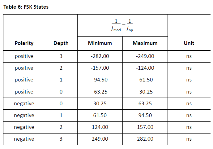
WPC 표준문서 Qi-v1.3.x-comms-physical 문서에 보면 전송주파수의 주파수 차를 어떻게 할 것인지 8개의 Depth로 표기가 되어 있다. 전력전송 주파수를 기준으로 + 또는 - 방향으로 시간차를 두고 변조를 하면 0과 1로 구분할 수 있다.
In the WPC standard document Qi-v1.3.x-comms-physical, there are 8 depths for the frequency difference of the transmission frequency. If the modulation is staggered in the + or - direction relative to the power transmission frequency, it can be separated into 0 and 1.
이를 가지고서 LTSPICE로 간단히 시뮬레이션을 가정하면 이렇게 나타낼 수 있다. Full Bridge Inverter나 Half Bridge Inverter까지 모델링해서 할 수 있으나 여기서는 간단히 구성하였다.
Assuming a simple simulation with LTSPICE, this is what it looks like. You can model a full bridge inverter or even a half bridge inverter, but this is a simple configuration.

변조시키기 위한 기본 시그널 파형 V1과 V2는 다음과 같이 정의하였다. 동작주파수 120kHz이고 천이 주파수는 116kHz이다.
The basic signal waveforms V1 and V2 to modulate are defined as follows. The operating frequency is 120 kHz and the transition frequency is 116 kHz.

이에 대한 최종 변조 출력은 V(fsk_m)이고 공진 Cap.과 코일간의 노드에서 보이는 파형은 V(n002) 이다.
The final modulation output for this is V(fsk_m) and the waveform seen at the node between the resonant Cap. and the coil is V(n002).

V(n002)노드에서의 주파수 스펙트럼으로 보면 다음과 같다.
The frequency spectrum at node V(n002) looks like this.

120kHz 주파수 대역을 확대하면 다음과 같다.
Zooming in on the 120 kHz frequency band looks like this.
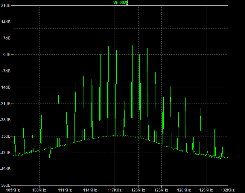
여기서 FSK 통신 시간에는 ASK 통신은 하지 않는다. 좌측점선 세로축이 116kHz 주파수, 우측점선 세로축이 120kHz이다. 송출한 신호와 비교해서 전력수신부의 검파회로 통해서 얻은 출력은 다음과 같이 확인할 수 있다.
Note that there is no ASK communication during FSK communication time. The left dotted vertical axis is the 116kHz frequency and the right dotted vertical axis is 120kHz. Compared to the transmitted signal, the output obtained through the power receiver's sampling circuit can be seen as follows.

위의 회로는 LTSPICE 통해서 구현한 시뮬레이션 모델이므로, 업무에 활용하기 위해서 실제 회로에 근접하도록 세부 데이터를 조정하거나 동작 개념을 이해하기 위해 파라미터로 해석도 가능하니 시도해 보기 바란다.
Since the above circuit is a simulation model implemented through LTSPICE, it is possible to adjust the detailed data to be close to the actual circuit for business use or to interpret the parameters to understand the operation concept, so please try it.


댓글